
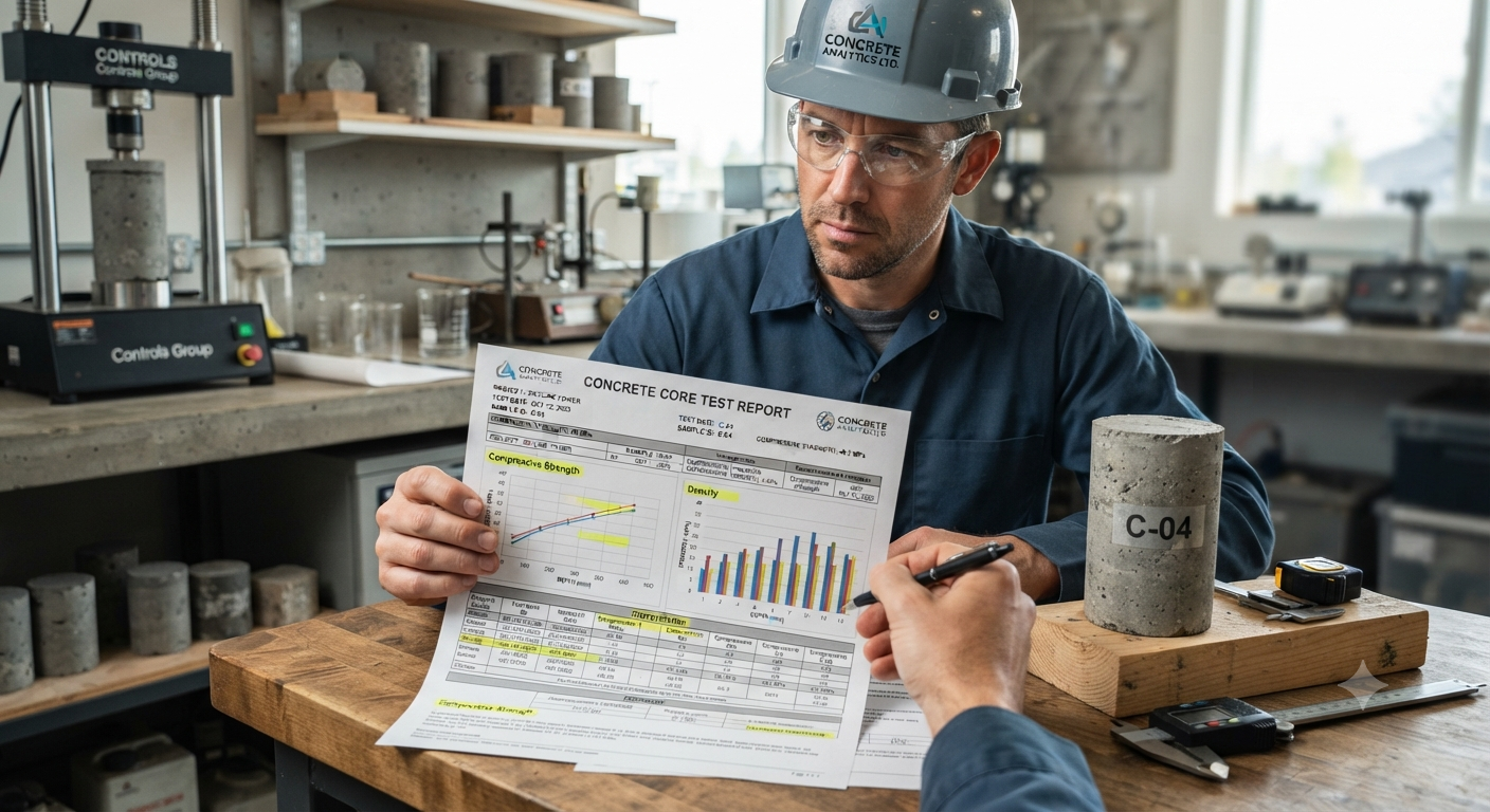
Target-Related Keywords & People Also Ask (PAA) Integration
-
Target-Related Keywords: concrete core cutting test, core strength calculation, IS 516 provisions for core test, structural integrity test India, equivalent cube strength, concrete core acceptance criteria.
-
People Also Ask (PAA) Addressed:
-
What is the acceptance criteria for a concrete core test?
-
How do you calculate core compressive strength from test results?
-
What are the IS code provisions for concrete core cutting?
-
Why do core test results differ from standard cube test results?
-
What is the correction factor for core height-to-diameter ratio?
-
Introduction
In the landscape of modern Indian construction—spanning high-rise residential towers in Mumbai and Bangalore to rapid metro rail infrastructure developments—ensuring structural safety is paramount. When standard cube test results fail to meet design expectations, or when evaluating older, distressed, or heritage structures during a structural audit, engineers turn to a definitive diagnostic tool: the concrete core test.
Conducted under strict guidelines, this destructive yet localized testing method extracts cylindrical specimens directly from structural members like columns, beams, and slabs. However, generating the laboratory report is only half the battle. Interpreting the concrete core test report requires a deep understanding of structural codes, geometry correction factors, moisture conditions, and acceptance criteria specified under Indian Standards (such as IS 516 and IS 456).
This comprehensive guide breaks down every section of a standard concrete core test report, equipping site engineers, structural consultants, and quality control professionals with the knowledge to make safe, code-compliant decisions.
1. Understanding the Basics: What is a Concrete Core Test?
A concrete core test involves drilling a cylindrical specimen out of hardened concrete using a diamond-impregnated core barrel. Driven by specialized core cutting services, this procedure is typically deployed when:
-
Low Cube Strength: Standard $150\text{ mm} \times 150\text{ mm} \times 150\text{ mm}$ site cubes cast during pouring show compressive strengths below the characteristic strength ($f_{ck}$).
-
Structural Distress: Cracking, spalling, or deflection occurs in buildings due to aging, overloading, or environmental degradation.
-
Durability and Quality Audits: Real estate buyers, builders, or municipal authorities mandate structural health checks for buildings in seismic zones or coastal belts (e.g., Mumbai, Chennai, Kolkata).
-
Unauthorized Modifications: Assessing load-bearing capacities when commercial spaces or apartments undergo unauthorized structural changes.
The extracted core provides a true representation of the concrete actually placed, compacted, and cured inside the structural element, accounting for real-world site conditions that standard lab-cured cubes miss.
2. Anatomy of a Standard Concrete Core Test Report
When a laboratory certified by the National Accreditation Board for Testing and Calibration Laboratories (NABL) or an approved engineering agency issues a report, it follows a structured format. To interpret it accurately, you must navigate through several key sections:
A. General Information and Metadata
-
Client Name and Project Details: Identifies the project (e.g., a commercial complex in Gurugram or a residential society in Pune).
-
Date of Sampling and Testing: Critical for calculating the exact age of the concrete at the time of testing.
-
Location/Member Identification: Specific coordinates or structural tagging (e.g., "Core extracted from Ground Floor Column C12 between Grid A and B").
-
Visual Description: Initial condition notes, such as the presence of honeycombing, aggregate distribution, or embedded reinforcement.
B. Physical Measurements (Dimensions and Geometry)
-
Diameter ($d$): Typically 50 mm, 100 mm, or 150 mm, depending on the maximum size of the coarse aggregate and congestion of steel reinforcement.
-
As-Received Length ($L_1$): The length of the core immediately after extraction.
-
Capped Length ($L_2$): The length after preparation (sawing and capping with sulfur or high-strength gypsum mortar) to ensure parallel, flat load-bearing surfaces.
-
Length-to-Diameter Ratio ($L/D$): A vital parameter that dictates the application of geometrical correction factors.
3. Step-by-Step Guide to Interpreting Core Strength Calculations
A common misconception is that the maximum crushing load divided by the cross-sectional area gives the final strength. In reality, multiple correction factors must be applied according to IS 516 (Part 4 / relevant sections) or SP 24.
Step 1: Calculate Apparent Compressive Strength
Where:
-
$P =$ Ultimate breaking load in Newtons ($N$)
-
$A =$ Cross-sectional area of the core specimen in square millimeters ($\text{mm}^2$)
Step 2: Apply the Length-to-Diameter ($L/D$) Correction Factor
Standard test cylinders have an $L/D$ ratio of $2.0$. However, concrete cores extracted from slabs or shallow beams often have an $L/D$ ratio significantly less than $2.0$ (frequently $1.0$ or $1.5$). Because shorter cores yield artificially higher apparent compressive strengths due to end-restraint friction from testing machine platens, a correction factor must be applied.
According to standard practice, if the $L/D$ ratio is less than $2.0$, multiply the apparent strength by the appropriate correction factor:
-
For $L/D = 2.0$: Factor = $1.00$
-
For $L/D = 1.75$: Factor = $0.98$
-
For $L/D = 1.50$: Factor = $0.95$
-
For $L/D = 1.25$: Factor = $0.93$
-
For $L/D = 1.00$: Factor = $0.87$
Pro Tip: Always verify whether the testing laboratory has already multiplied the raw value by the $L/D$ correction factor or if it needs to be applied manually by the structural consultant.
Step 3: Apply Diameter Correction Factors
If the core diameter is small (e.g., $50\text{ mm}$ cores used in congested structural elements), aggregate bridging and boundary effects can influence results. Some standards require a diameter correction factor, typically multiplying by $1.06$ for $50\text{ mm}$ diameter cores compared to standard $100\text{ mm}$ cores, though this depends on specific testing protocols and maximum aggregate size (MAS).
Step 4: Moisture Condition Correction
The moisture state of the core during testing drastically affects compressive strength:
-
Saturated Cores: Cores tested in a wet or saturated condition can show strengths 10% to 15% lower than air-dry cores.
-
Air-Dried Cores: If tested dry, moisture gradients can weaken the outer skin.
Indian standards generally recommend soaking the core in water for 40 hours prior to testing to achieve a standardized saturated condition, or testing under specified moisture conditions as agreed upon in the project quality plan.
4. Indian Standards and Acceptance Criteria: What Does IS 456 Say?
Interpreting numbers in isolation is useless without benchmarking them against regulatory frameworks. In India, IS 456:2000 (Plain and Reinforced Concrete - Code of Practice) governs structural design and sets clear rules for core test acceptance.
Clause 17.5.3 of IS 456:2000 Compliance
When core tests are conducted to check concrete quality in a suspect zone, IS 456 dictates the following acceptance criteria:
-
Equivalent Cube Strength ($f_{eq}$): The strength of the concrete indicated by the core test shall be calculated by multiplying the corrected core strength by specific factors (historically, a factor translating cylinder strength to equivalent cube strength, approximately $1.25$ to $1.33$, depending on the standard interpretation).
-
The 85% Rule: The concrete in the member represented by the core test is considered acceptable if the average equivalent cube strength of the cores is at least 85% of the characteristic compressive strength ($f_{ck}$) of the specified grade (e.g., for M25 concrete, $85\%$ of $25\text{ N/mm}^2 = 21.25\text{ N/mm}^2$).
-
Individual Core Threshold: No single core strength should fall below 75% of the specified characteristic strength.
+-------------------------------------------------------------+
|                IS 456 ACCEPTANCE THRESHOLDS                 |
+-------------------------------------------------------------+
|  Average Core Strength  >=  85% of Specified f_ck           |
|  Individual Core Strength >= 75% of Specified f_ck          |
+-------------------------------------------------------------+
5. Real-World Indian Case Studies & Scenarios
To ground these technical concepts, let us look at two common field scenarios encountered by structural engineers across Indian metros:
Scenario A: High-Rise Residential Tower in Noida (Grade M30)
-
Situation: During routine casting of the 15th-floor columns of an M30 grade mix, 28-day cube test results averaged $24\text{ N/mm}^2$, raising alarms for the structural consultant.
-
Action: Core cutting was ordered. Three $100\text{ mm}$ diameter cores were extracted.
-
Report Findings:
-
Core 1: $27.5\text{ N/mm}^2$
-
Core 2: $26.8\text{ N/mm}^2$
-
Core 3: $28.1\text{ N/mm}^2$
-
Average Equivalent Cube Strength: $27.4\text{ N/mm}^2$
-
-
Interpretation: Although lower than the characteristic strength of $30\text{ N/mm}^2$, $27.4\text{ N/mm}^2$ is greater than 85% of M30 ($25.5\text{ N/mm}^2$). Furthermore, individual values exceed the $75\%$ threshold ($22.5\text{ N/mm}^2$).
-
Conclusion: The structural engineer accepted the concrete in-situ, noting that standard site cube curing procedures likely suffered from moisture loss compared to the well-cured interior of the column.
Scenario B: Commercial Retrofit Project in Bengaluru (Grade M20)
-
Situation: A 15-year-old commercial building undergoing a structural audit for vertical expansion showed signs of dampness and seepage.
-
Report Findings: Core samples extracted from primary beams yielded an average equivalent cube strength of $14\text{ N/mm}^2$ against an original design mix of M20 ($20\text{ N/mm}^2$).
-
Interpretation: The average strength is $70\%$ of $f_{ck}$, falling well below the 85% acceptance mark.
-
Conclusion: The report indicated carbonation-induced degradation and loss of alkalinity. The structural consultant recommended structural retrofitting using carbon fiber wrapping (CFRP) and micro-concrete grouting before loading additional floors.
6. Common Pitfalls and Anomalies in Core Test Reports
When reviewing a laboratory report, watch out for red flags that can skew data interpretation:
-
Damage to Reinforcement: If the core hits a large reinforcing bar during extraction, the bar can act as a stress concentration point, causing premature failure of the sample. Such cores should be discarded, and a new core drilled nearby.
-
Honeycombing and Voids: Visual remarks in the report regarding poor compaction or honeycombing mean the core is unrepresentative of homogeneous structural concrete, pointing to localized execution flaws.
-
Incorrect Capping: Uneven capping surfaces lead to eccentric loading during testing, resulting in artificially low compressive strength readings. Always cross-check the perpendicularity and flatness notes in the report.
Summary Checklist for Engineers
| Checklist Item | Standard Requirement | Your Report Value | Status |
| IS Code Reference | IS 516 / IS 456 | Checked | [Pass/Fail] |
| L/D Ratio Correction | Applied accurately | Checked | [Pass/Fail] |
| Average Strength | $\ge 85\%$ of $f_{ck}$ | Checked | [Pass/Fail] |
| Individual Strength | $\ge 75\%$ of $f_{ck}$ | Checked | [Pass/Fail] |
| Rebar Interference | None / Accounted for | Checked | [Pass/Fail] |
Conclusion
Interpreting concrete core test reports is a critical engineering responsibility that bridges field execution with analytical structural safety. By carefully evaluating length-to-diameter ratios, moisture states, and applying the acceptance thresholds mandated by IS 456, engineers can accurately judge whether a structure stands safe or requires intervention. For reliable core extraction and precise diagnostic services adhering to Indian Standards, reach out to industry experts at [email protected] to ensure your next construction or structural audit project meets the highest benchmarks of quality and safety.