
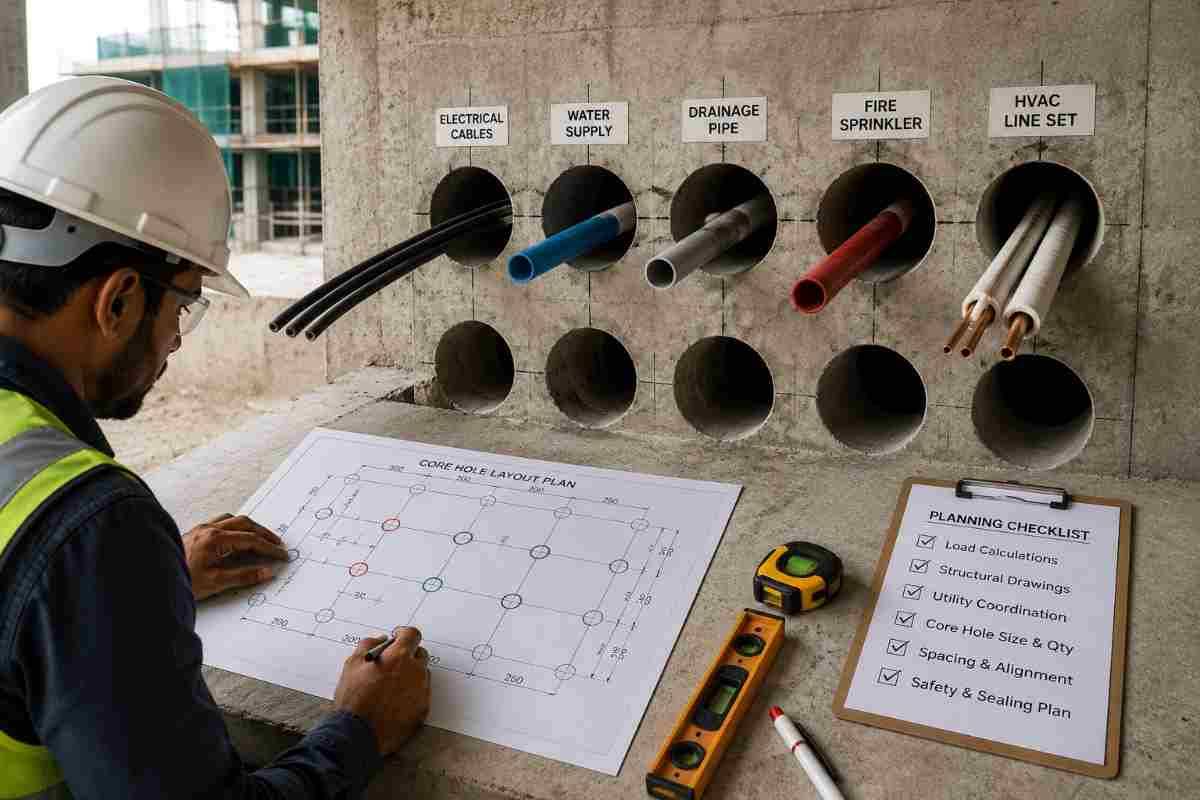
When constructing modern commercial facilities, industrial complexes, high-rise residential towers, or refurbishing existing concrete structures, routing Mechanical, Electrical, and Plumbing (MEP) utilities is one of the most critical stages of building development. High-density utility corridors require dozens—sometimes hundreds—of precision openings to allow HVAC ducts, electrical conduits, plumbing pipes, fire suppression lines, and fiber-optic communication cables to pass seamlessly through concrete slabs, sheer walls, and structural beams.
Precision core drilling using diamond core bits provides clean, cylindrical penetrations without causing structural micro-cracking or acoustic vibration damage. However, the physical drilling process is only the final execution step. The true success of any utility installation depends almost entirely on pre-drilling planning, spatial layout, structural assessment, and accurate subsurface scanning.
Failing to plan core holes properly before running multiple utility lines leads to severe consequences: structural weakening, compromised fire ratings, expensive rerouting, damaged tension cables or live conduit lines, and costly project delays.
In this comprehensive guide, Core Cutting India walks you through the essential engineering and execution steps required to accurately plan, scan, layout, and drill core holes for multi-utility installations.
1. Why Pre-Planning Core Holes is Essential for Multi-Utility Installations
When a single pipe needs to pass through a wall, adjusting the position by a few inches might be simple. However, when managing multiple utility lines running parallel through tight service corridors, shaft walls, or slab penetrations, spatial margins disappear rapidly.
       [ Core Hole Planning Lifecycle ]
  +------------------------------------------+
  | 1. Utility Load & Clearance Mapping      |
  +------------------------------------------+
                      |
                      v
  +------------------------------------------+
  | 2. GPR & X-Ray Subsurface Scanning       |
  +------------------------------------------+
                      |
                      v
  +------------------------------------------+
  | 3. Structural & Edge Clearance Layout     |
  +------------------------------------------+
                      |
                      v
  +------------------------------------------+
  | 4. Precision Diamond Core Drilling       |
  +------------------------------------------+
Key Reasons Pre-Planning is Critical:
-
Structural Integrity: Concrete slabs and walls rely on internal steel rebar networks and post-tensioned (PT) tendons. Unplanned drilling can slice through critical structural reinforcement, reducing the structural load capacity.
-
Avoiding Spatial Congestion: Electric lines, water pipes, gas lines, and drain pipes have distinct insulation, slope, and clearance requirements. Poor planning results in utility overlap and clashes.
-
Fire Containment & Code Compliance: Penetrations must accommodate firestop assemblies. Holes drilled too close together prevent adequate installation of fire-rated sealants and collars.
-
Thermal & Acoustic Insulation Space: Chilled water lines, hot water pipes, and steam lines require thick insulation jackets. If core holes are spaced based only on pipe diameter rather than insulated outer diameter, the lines will not fit.
2. Step 1: Mapping Utility Requirements & Pipe Spacing
Before marking a single center-point on the floor or wall, assemble the complete combined services drawing (CSD) or Building Information Model (BIM).
A. Calculate Nominal vs. Effective Diameters
The single most common error in planning core holes for multiple utilities is sizing the core bit to the nominal pipe size rather than the total required diameter.
-
Bare Pipe Outer Diameter (OD): The base structural size of the pipe or conduit.
-
Insulation Thickness: Thermal insulation (e.g., elastomeric foam, mineral wool) adds anywhere from 25 mm to 75 mm around the circumference.
-
Annular Space for Firestopping: Standard building codes require an annular gap (typically 12 mm to 25 mm) around the pipe to apply firestop sealant, expanding intumescent wraps, or mechanical sleeves.
$$\text{Required Core Hole Diameter} = \text{Pipe OD} + (2 \times \text{Insulated Thickness}) + (2 \times \text{Annular Firestop Clearance})$$
B. Standard Spacing Between Multiple Core Holes
When drilling multiple adjacent holes in a row (a "bank" or "cluster"), structural integrity dictates minimum web spacing (the solid concrete remaining between adjacent holes).
| Core Hole Diameter (D) | Minimum Web Distance (S) | Purpose / Considerations |
|
Small ($\le 50\text{ mm}$) |
$100\text{ mm}$ or $2D$ |
Small electrical conduits, sensor lines |
|
Medium ($50\text{ to } 150\text{ mm}$) |
$150\text{ mm}$ or $1.5D$ |
Water supply, drainage, medium power banks |
|
Large ($> 150\text{ mm}$) |
$200\text{ mm}$ or $2D$ |
HVAC ducts, large waste pipes, main risers |
Note: Always consult structural engineering guidelines before drilling clusters of holes larger than $150\text{ mm}$ in post-tensioned slabs.
3. Step 2: Conducting Advanced Subsurface Concrete Scanning
Never drill into a reinforced concrete slab or wall blind. Modern concrete elements house embedded hazards that, if damaged, threaten structural stability and job site safety.
Embedded Objects to Identify:
-
Rebar mats (primary structural reinforcement)
-
Post-tension cables (PT tendons under extreme pressure)
-
Pre-existing embedded electrical conduits
-
Fiber-optic lines and telecommunication runs
-
Underground radiant heating or cooling loops
Modern Scanning Technologies
To locate embedded objects accurately, specialized scanning teams use two complementary techniques:
1. Ground Penetrating Radar (GPR)
GPR sends high-frequency electromagnetic radar pulses into the concrete and reads the reflected signals.
-
Depth Capabilities: Accurately scans up to $400\text{ mm}$ to $600\text{ mm}$ deep in standard concrete.
-
Benefits: Provides real-time 3D mapping of rebar grids, conduits, and post-tension cables without emitting ionizing radiation.
2. X-Ray Imaging (Radiography)
Where extreme precision is needed in dense or congested slabs, industrial concrete X-ray imaging provides detailed photographic records of internal steel placements.
-
Benefits: High image clarity.
-
Limitations: Requires access to both sides of the slab/wall and site evacuation due to radiation safety protocols.
At Core Cutting India, our teams combine high-frequency GPR scanning with digital utility mapping to guarantee clean core placements that bypass structural steel and live electrical runs.
4. Step 3: Layout Guidelines and Structural Safety Margins
Once subsurface scans are mapped onto the concrete surface using durable layout markers, adjust the core hole centerlines to maintain required safety margins.
       Typical Core Hole Clearance Layout
  +-----------------------------------------------+
  |                                               |
  |   ( Beam / Column Core Zone )                 |
  |     +-------------------------+               |
  |     |  CRITICAL CRACK ZONE    |               |
  |     |  [NO DRILLING PERMITTED]|               |
  |     +-------------------------+               |
  |                  |                            |
  |                  | (Min. 300 mm / 2x Thickness)|
  |                  v                            |
  |         ( Core Hole 1 )    ( Web )   ( Core Hole 2 )
  |          +-----------+     +-----+    +-----------+
  |          |  (  O  )  |<--->|     |<-->|  (  O  )  |
  |          +-----------+     +-----+    +-----------+
  |                             >=150mm           |
  |                                               |
  +-----------------------------------------------+
A. Distance from Beams, Columns, and Drop Panels
-
Critical Shear Zones: Avoid drilling core holes within $300\text{ mm}$ (or twice the slab thickness) of supporting column faces, drop panels, or beam connections unless explicitly cleared by structural engineers. These locations experience peak shear stress.
-
Mid-Span Slabs: The center third of slab spans is generally preferred for utility penetrations, provided tension steel remains uncompromised.
B. Clearance Around Post-Tension (PT) Tendons
Damage to a post-tension cable can cause violent concrete spalling, structural collapse, and severe injury.
-
Safety Buffer: Maintain a minimum offset of $100\text{ mm}$ to $150\text{ mm}$ from the outer edge of any identified PT cable path.
-
Parallel Runs: If core holes run parallel to a PT tendon strand, clear the entire corridor using GPR before anchoring core drill rigs.
C. Slab Edge Clearances
Drilling too close to an unsupported slab edge can cause perimeter cracking or blowout. Maintain an absolute minimum clearance of $150\text{ mm}$ from any free structural edge or expansion joint.
5. Step 4: Step-by-Step Core Hole Execution Workflow
When utility mappings, GPR scans, and structural clearances are finalized, execute the core cutting operation according to a strict standard operating procedure (SOP).
Phase 1: Precision Surface Marking
-
Draw actual core hole outer circumferences (not just centerlines) directly on the concrete using industrial markers.
-
Mark rig anchor points away from embedded conduits or rebar.
-
Label each hole with its designated utility system (e.g., "ELEC-01", "PLUMB-04", "HVAC-02").
Phase 2: Equipment Setup & Stabilization
-
Rig Mounting: Secure the core drilling stand using heavy-duty anchor bolts or vacuum suction bases for smooth, finished surfaces.
-
Alignment & Plumb Check: Verify that the core drill barrel is perpendicular ($90^\circ$) to the surface—or at the intended angle—to prevent offset exits on thick walls/slabs.
Phase 3: Water Control & Slurry Containment
Diamond core bits require continuous water cooling to protect the diamond segment matrix and flush out concrete slurry.
-
Install slurry collection rings and industrial wet vacuum systems to prevent slurry from seeping onto floors below or contaminating electrical trays.
Phase 4: Core Penetration & Core Removal
-
Initiate drilling at lower speed until the diamond bit seats evenly into the concrete surface.
-
Maintain steady downward feed pressure to allow the diamonds to cut efficiently through reinforced steel bars without binding.
-
Once the full depth is penetrated, carefully extract the concrete core slug and inspect the interior walls of the penetration.
6. Common Mistakes to Avoid in Multi-Utility Core Hole Planning
Avoid these common pit-falls during site planning:
-
Ignoring Slope for Gravity Drainage: Sewer and condensate drain lines require a continuous downward slope ($1\%$ to $2\%$). Core holes drilled across multiple walls must drop in elevation progressively; drilling them all at identical heights will cause drainage failures.
-
Over-clustering Holes: Concentrating too many large-diameter holes in one region of a structural slab creates a continuous weak line, transforming an engineered slab into a segmented shear plane.
-
Drilling Anchor Holes Blindly: Project teams often scan the main core location carefully but drill the core rig base anchor bolt blindly into an embedded electrical line. Always scan the anchor position alongside the main hole.
-
Neglecting Future Expansion: When laying out multi-utility runs, include $15\%$ to $20\%$ spare core penetrations (capped for fire safety) to allow future utility additions without requiring secondary mobilization.
7. People Also Ask (PAA) & Frequently Asked Questions
Q1: How far apart should core holes be drilled in a reinforced concrete slab?
As a general standard rule, the solid concrete space (web) between adjacent core holes should equal at least $1.5 \times$ to $2 \times$ the diameter of the larger hole, with an absolute minimum gap of $100\text{ mm}$ to $150\text{ mm}$. Always consult structural drawings before drilling continuous linear hole arrays.
Q2: What happens if core drilling cuts through structural rebar?
Cutting through primary structural rebar reduces the load-bearing capacity of the slab or wall. If rebar is inadvertently cut, a structural engineer must assess the damage. Retrofit solutions—such as carbon fiber wrapping (CFRP), steel plate bonding, or structural framing—may be required to restore design integrity.
Q3: How do you plan core hole locations for MEP utility lines?
MEP core hole planning involves reviewing Combined Services Drawings (CSD) or BIM models, calculating total pipe diameters including thermal insulation and firestop gaps, conducting GPR subsurface scans, and aligning holes to satisfy slope, structural clearance, and edge-distance standards.
Q4: Why is concrete scanning necessary before core drilling?
Concrete scanning via Ground Penetrating Radar (GPR) detects hidden structural steel, post-tension cables, live electrical conduits, and plumbing runs. Scanning protects workers from high-voltage hazards, prevents structural failure, and avoids expensive repairs caused by severed utilities.
8. Partner with Core Cutting India for Precision Utility Hole Drilling
Planning and executing core penetrations across multi-utility corridors demands engineering insight, advanced subsurface scanning technology, and heavy-duty diamond cutting machinery.
At Core Cutting India, we provide comprehensive concrete cutting, diamond core drilling, slab sawing, and GPR concrete scanning services tailored to commercial, industrial, and infrastructure projects across India.
Why Choose Core Cutting India?
-
High-Precision Diamond Drilling: Core hole diameters ranging from $25\text{ mm}$ up to $600\text{ mm}+$ at variable depths.
-
Advanced Concrete Scanning: High-resolution GPR scanning to detect rebar, PT cables, and embedded utilities prior to drilling.
-
Clean & Noise-Controlled Operations: Dustless, low-vibration wet-drilling setups with complete slurry containment.
-
Experienced Workforce: Fully trained technicians operating strictly under structural safety and site security standards.
Get Expert Core Drilling Services Today
Need accurate, clean core holes for your next plumbing, electrical, or HVAC installation project? Contact our engineering team to discuss your project requirements, request an on-site evaluation, or receive a free competitive estimate.
-
Website: https://corecuttingindia.com/
-
Phone / WhatsApp: +91 70096 79903
-
Services Available: Commercial Core Drilling, Structural Scanning, Slab Sawing, Wall Sawing, and Chemical Anchoring nationwide.